Cathode Phase Inversion, Otto H. Smith
Departments of Physics and Zoology, University of Minnesota, Minneapolis, Minnesota, (Received July 17, 1941)
Application of cathode phase inversion previously described is made to several practical circuits including symmetrical cathode-ray oscillograph amplification, high fidelity d.c. amplification, and differential or mixer amplifier operation. The theory of a symmetrical degenerative attenuator modification of the basic circuit is developed and practical applications are described.
The cathode phase inversion amplifier [1] (Fig. 1) is a form of self-inverting push-pull amplifier which is now finding considerable application in scientific [2, 3] and in commercial [4] apparatus. Essentially, the cathode phase inversion stage is a conventional push-pull amplifier stage in which the cathode resistor R_K, common to both tubes, has been increased until the product of its resistance with the mutual conductance of either amplifier tube is large with respect to unity, and in which the cathode return (-) is biased to a suitably high negative potential with respect tot he control grid. Under the circumstances, a signal applied to either control grid appears almost symmetrically amplified, but in opposite phase, in the two plate circuits.
Since the degenerative voltage which is produced in the common cathode resistance when a signal is applied to one grid serves as an input signal in reversed phase to the second grid, amplification is not lost in the phase inversion process but totals between the two output circuits approximately as much as would be obtained with a single tube non-inverting amplifier.
For sufficiently large values of the common cathode resistance R_K, the amplified signal splits symmetrically between the two output circuits, but as the cathode resistance becomes small, a larger fraction of the total output signal appears in the plate circuit of the tube to which the input signal is applied. The ratio of the plate signal magnitude in the input tube to that in the other plate circuit is given by the expression
E_p1 / E_p2 = 1+1/G_m*R_K [eq.1]
where G_m is the mutual conductance of one tube and R_K is the cathode resistance. Tubes and plate circuits are assumed identical.
Because this phase inversion is accomplished without loss of amplification in the stage, the circuit is economically adapted to ordinary audio amplifier use. Here it can be employed in the final power stage, as well as in one or more of the preceding stages. In any case it eliminates the push-pull input transformer, and, when used in the low level stages, permits operation from quite poorly filtered power supplies because of the degenerative self-filtering action of the circuit.

While the negative cathode bias voltage, by means of which the control grids are held at earth potential in Fig. 1, is a luxury available in many research instruments, its presence is unnecessary if, as is the case in the capacitance-coupled and many d.c. amplifiers, the grids may be at a positive potential. In these cases the circuit of Fig. 2 is used, the cathode return being made to earth and a positive bias from a bleeder resistor supplying the control grids. The bleeder, incidentally, need carry no appreciable current, since no current flows in the grid circuit. If pentodes or tetrodes are used, their control grids may conveniently be supplied from the same divider which energizes their screens.
The modification of the circuit shown in Fig. 3 is peculiarly adapted for oscilloscope use, directly coupled to either magnetic or electrostatic deflection cathode-ray tubes, since here the circuit serves not only as a phase inverter and final amplifier but also provides a means of shifting the axis of the beam to either limit of the tube's screen without requiring increased linear output characteristic of the final amplifier for complete tube face coverage.
On investigation of the reltionship obtaining in the basic circuit Fig. 1, it will be seen that in response to a change in the average control grid potential, the average plate voltage of the two tubes in one stage changes in the ratio of the parallel resistance of the two plate resistors to the resistance of the common cathode resistor. As this ratio is normally small and can be reduced even below unity, the circuit is especially suited for use as a direct-coupled amplifier using voltage divider coupling as illustrated in Fig. 4. Suppose the amplifier were to consist of three stages of 100 gain each, and the resistor ratio were allowed to remain as high as 3. In this case, the final stage drift occasioned by a 0.1-millivolt change variation in the average input grid potential would appear as 10^-4 * 3^3, or 2.7 millivolts drift in the average output potential. Meanwhile the amplification of the system would be one million, so that the response to a difference of potential between the two input grids of 0.1mV would be 100 volts. Asymmetric variations of current in the input tubes due to emission, microphonic, or other disturbances would, of course, be fully amplified along with the signal.
Additional advantages of this type of amplifier are that it responds equally well to a push-pull input, a single-sided input with one input terminal grounded, or to the difference between two indepdendet inputs each applied to a separate grid. Where the absolute value of the input potential is being measured, and where conditions make it awkward to connect the standard potentiometer either between the unknown source and earth or between it and the grid, the potentiometer can be plugged into the opposite grid circuit and, within a small ascertainable error, will read directly, and can simultaneously take up any amplifier drift. It will be noted, further, that so long as heather-cathode type tubes are used, any number of stages can be supplied from one filament source and one plate source. As all cathodes operate at approximately the same potential there is no cascading of potentials. This form of amplifier has been found of considerable usefulness in studying bioelectric phenomena.
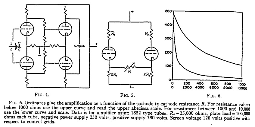
Fig. 6. Ordinates give the amplification as a function of the cathode to cathode resistance R. For resistance values below 1000 ohms use the upper curve and read the upper abscissa scale. For resistances between 1000 and 10,000 use the lower curve and scale. Data is for amplifier using 1852 type tubes. R_K = 25,000 ohms, plate load = 100,000 ohms each tube, negative power supply 250 volts, positive supply 780 volts. Screen voltage 2120 volts positive with respect to control grids.
In this circuit, as in most push-pull systems, attenuation presents a serious problem, since exactly equal loss must be inserted into each side of the circuit to keep potential differences symmetrical, and because two variable elements must usually be inserted into each stage which is to be controlled. Since the total attenuation usually cannot be accomplished in one stage, this means a multiplicity of ganged resistance elements. In the case of d.c. amplifier, further difficulty arises because attenuation must not occasion baseline shift. These troubles can be avoided by the slight change in the fundamental circuit illustrated in Fig. 5. Here the common cathode resistor R_K has been replaced by separate ones (each having twice the original resistance) joined by a single variable element. It will be obvious that, as a limiting condition, this circuit passes over into the one illustrated in Figs. 1 and 2 when R becomes equal to zero, but when R becomes infinite, the over-all amplification becomes about equal to the ratio of the plate resistance of one tube to that of one cathode resistor. This ratio will usually be from 3 to 5. Between the two extremes the amplification changes continuously.
The approximate amplification may be calculated for any value of the attenuating resisor R with the aid of the formula
A = ( R_p * R_x * G_m ) / ( R_p + R_x + ( G_m * R_1 * R_p ) + R _1
where
R_1 = ( 2 * R * R_K ) / ( R + 4 * R_K )Here A the useful amplification is given in terms of R_p the dynamic plate resistance of one tube. R_x the resistance of one load resistor, and G_m the transconductance of one tube. This formula applies primarily to triodes and gives less accurate results for pentodes and tetrodes unless the transconductance to the scnreen is taken into account.
Upon inspection of this formula it will be seen that the introduction of resistance decreases amplification rapidly at first, then more and more slowly as the total amplification becomes smaller. Used with an ordinary logarithmic control, very nice control can be maintained. Fig. 6 illustrates quantitatively the range of over-amplification available from a stage of 1852 pentodes used to drive a rathode-ray tube of 7-inch variety.
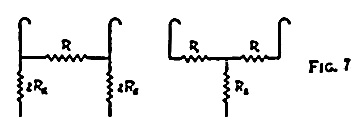
It might be pointed out that the circuit A (Fig. 7) is electrically replaceable by the circuit B (Fig. 7) (by the delta-star transformation) if R_1 = ( 2 * R * R_K ) / ( R + 4 * R_K ), and R_2 = ( 4 * (R_K)^2 ) / ( R + 4 * R_K )
This allows convenient calculation of the output asymmetry along with any desired amount of attenuation since the calculated equivalent value of R_2 can be inserted in Eq. (1). As only one resistor element need be introduced per stage, up to three stages can easily be controlled from one knob, thus eliminating stage changing or other complicated maneuvers. The amplification of the whole amplifier is constant enough at all but the highest gains to permit pre-calculation of the resistor constants and their construction into a tapped pad to be calibrated directly in terms of over-all gain. This stability results from the effective negative feedback introduced by the use of the cathode to cathode resistor.
As usual, where attenuation is achieved through use of negative feedback, the linearity of the amplifier improves as greater attenuation is introduced, and consequently a long linear voltage output charactertistic accompanies even moderate attenuation. This is illustrated by Fig. 8 which plots the plate to plate output voltage against unilaterally applied input voltage at several attenuations for a typical 6J7G cathode-ray pre-amplifier stage fed from a 225-volt power supply. The pentodes, ordinarily bad offenders in respect of linearity, are seen to give 260 volts of linear output at a stage gain of 50, while they produce 300 volts of output at 14 gain. It should be remembed, however, that this linearity is achieved as the result of cathode feedback, and consequently is current linearity. This is to advantage in certain systems -- like magnetically deflected cathode-ray tubes -- where current must remain constant independent of frequency; it is, however, a detriment to high frequency operation of capacitative systems, like electrostatically deflected cathode-ray tubes. Even in this case, however, frequency linearity is easily obtained without compensation up to 10,000 cycles, and, with care, as high as 14,000 cycles.
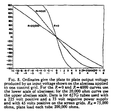
Fig. 8. Ordinates give the plate to plate output voltage produced by an input voltage shown on the abscissa applied to one control grid. For the R=0 and R=4000 curves use the lower scale of abscissae; for the 20,000 ohm curve use the upper abscissa scale. Data is for 6J7G tubes used with a 225 volt positive and a 75 volt negative power supply with 45 volts positive on the screen grids. R_K = 75,000 ohms, plate load each tube 200,000 ohms.
In those cases where it is of no consequence that an amplifier shall not respond well below, perhaps, 10-20 cycles per second, the cathode resistor may be replaced by a choke, or, if the attenuation method is to be employed, by a pair of chokes. In this case the grids may be maintained at a convenient zero potential and yet have no large loss of plate supply potential in the common cathode resistors. Often a choke can be found having the correct d.c. resistance to bias the tubes; if not, it can be supplemented with small additive resistors.
Calculation of the necessary cathode resistance in any case is extremely simple. If no attenuator is to be employed, the value of R_K will be
R_K = R_c + V / I
where R_C is the published value of cathode resistor for ordinary push-pull operation, V is the voltage between control grids and the cathode return, and I is the desired value of total plate current for the two tubes. For use with the attenuator circuit, twice this resistance is inserted in each branch of the circuit.
[1] O. H. Schmitt, J. Sci. Inst. 15, 136 (1938).
[2] W. E. Rahm, Electronics, p. 11 (October, 1939).
[3] O. H. Schmitt, J. Sci. Inst. 15, 234 (1938).
[4] W. A. Geohagen, Electronics, p. 36 (November, 1940).
Material herein added and updated constantly; presented for inspirational and educational purposes per Fair Use.
Last modified 6 Mar 2026
